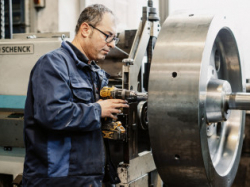
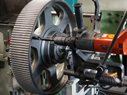
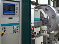
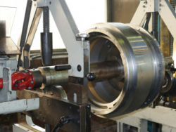
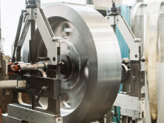
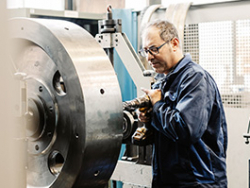
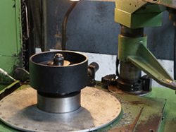
With the most modern, computer-controlled balancing machines from Schenck, we are able to balance rotationally symmetrical workpieces in one or two planes according to DIN ISO 21940-11 in quality grades G 16, G 6.3 or G 2.5.
The aim is to achieve optimum running quietness and minimum wear at maximum performance and absolute precision. The running maintenance is sustainably improved, the service life of the bearings and components is extended and the operational safety is increased.
Bearing forces and vibrations, shaft deformations and foundation loads are to be limited to the lowest possible values. Balancing reduces the unbalance and ideally eliminates it completely. To achieve this, mass balancing is necessary. Depending on the initial situation, weights are attached to the rotor or material is removed, for example by grinding, drilling or milling.
The balance quality and the measured residual unbalance are documented and, if desired, recorded in certificates according to DIN EN 10204. Standard drive elements, which are purchased from Asia with a balance quality of G 16, can also be rebalanced to a higher quality level on request.
In addition to balancing drive elements from our own production, we also offer contract balancing of customer-specific components. We offer this service for both individual rotors and series production. For this purpose, numerous balancing fixtures are available for a wide range of requirements.
Type | Manufacturer | Max. Ø | Max. weight | Procedure |
---|---|---|---|---|
H 3 U | Schenck | 800 mm | 300 kg | Dynamic balance bench |
130 HBA-BAE 0714 | Schenck | 800 mm | 500 kg | Vertical balancing machine |
H 5 U | Schenck | 2500 mm | 5500 kg | Dynamic balance bench |
The balancing quality G creates a comparability of the desired balancing quality of rotors of different sizes and weights.
In principle, heavier components may have a higher residual unbalance than lighter components with the same balance quality. The smaller the balance quality, the lower the residual unbalance remaining after balancing. However, the balancing process is more complex because the number of necessary balancing runs until the permissible residual unbalance is reached increases with small balancing grades.
The requirements for the balancing tolerance for rotors with rigid behaviour (rotationally symmetrical drive elements) are specified in the standard DIN ISO 21940-11. Part 11 of this standard contains a definition of balancing tolerances and balancing grades in addition to the necessary number of correction planes and methods for verifying residual unbalance. The quality level G is specified in mm/s and defines the maximum permissible path speed of the rotor centre of gravity.
Balancing grade | Rotor types / examples of components |
---|---|
G 2,5 | Medium and large electric motors and generators, compressors, computer drives, gas and steam turbines, machine tools, mechanical engineering in general |
G 6,3 | Small electric motors and generators, pulleys, flywheels, fans, pumps, centrifuges, water turbines, rollers for paper and printing machines, parts for process engineering, mechanical engineering in general |
G 16 | Drive shafts (propeller shafts, cardan shafts) with special requirements, parts of crushing and agricultural machines |
G 40 | Car components: Wheels, rims, wheel sets, cardan shafts and crankshafts |
Static balancing
The unbalance of the rotor is determined solely by gravity. The rotor
turns its heaviest point downwards in smooth-running bearings.
By adding or removing mass, the centre of gravity is shifted to the axis of rotation.
Determination of the unbalance: The rotor is supported on a roller stand in a light-running manner. Due to the unbalance (unequal mass distribution), the rotor turns so that the centre of gravity is below the axis of rotation due to the weight force. Now a balance can be created with magnetic weights or by removing material. The balancing of weights only takes place in one plane.
With our professional machinery we are able to statically balance drive pulleys up to a diameter of 750 mm, a width of 750 mm and 2,000 kg dead weight.
Permissible residual unbalance
The permissible residual unbalance is determined by the balancing grade, the weight of the rotor and its speed.
Dynamic balancing
The rotor is set in rotation by a machine. Transducers register the position and magnitude of the unbalance.
By adding or removing mass in two planes, the centre of gravity is shifted to the axis of rotation and the centre of gravity axis becomes equal to the axis of rotation.
Determination of the unbalance: The rotor is brought up to the test speed. Sensors measure the centrifugal forces and their angular position in the bearing. Software is used to determine the amount and position of the correction. Weight compensation is now provided in balancing planes 1 and 2.
With our Schenck balancing benches, we can dynamically balance drive
pulleys with a maximum diameter of 2,500 mm, a width of 800 mm and a
weight of up to 5,500 kg.
Balancing in one plane
Balancing only takes place in one plane. This can be done statically as well as dynamically.
Balancing in two planes
Balancing is carried out in two planes. This is only possible if the
rotor is sufficiently wide in relation to its diameter: outer diameter /
rim width <4
Flohr Industrietechnik GmbH - Im Unteren Tal 1 - 79761 Waldshut-Tiengen (Allemagne) - Téléphone : +49 (0)7751 / 8731-0 - info@flohr-industrietechnik.
Table des matiéres Contact Conditions générales de vente Mentions légales
Politiquede confidentialité Politiquede confidentialité courriel
Suivez-nous
sur : Facebook | Instagram | LinkedIn