Locking assemblies
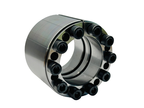
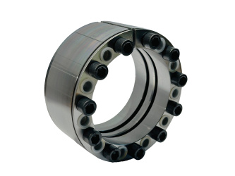
Locking assemblies are used in mechanical engineering to create a
frictional shaft-hub connection. The Locking assemblies connects the hub
of a gear, for example, to a shaft by means of a frictional connection.
This backlash-free connection between shaft and hub allows reliable
transmission of torques as well as axial forces. Depending on the design
of the clamping set, high bending moments can also be transmitted with
this type of connection.
Downloads
-
 Locking assemblies
(6017 KB)
Short info
- Easy assembly and disassembly
- Transmittable torque from 11 Nm to 1,870,000 Nm
- Nominal diameter from 6 mm to 800 mm
- Also available as stainless steel version
- Special designs for higher bending moments are available
Functional principle
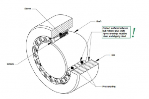
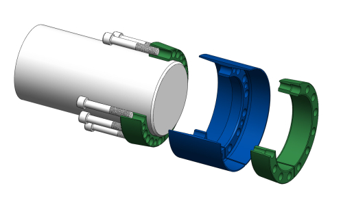
Locking assemblies consist of one or two conical pressure rings and a
conical clamping sleeve, depending on the design. By tightening the
clamping screws with the specified tightening torque, the conical
pressure rings are drawn onto the conical surface of the clamping
sleeve. This process creates a radial force both inward and outward. While the outside diameter increases, the diameter inside the clamping
sleeve decreases. This creates a frictional connection between the
locking assembly (cone clamping element) and the shaft as well as the
hub.
In contrast to a groove in conventional keyway connections, the stresses
at the shaft are distributed evenly over the entire contact surface of
the locking assembly. The uniform stress distribution produces a
reliable, free positional and, above all, wear-free connection. This
often leads to a smaller shaft size and therefore reduced weight of the
design.
Versions
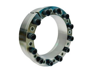
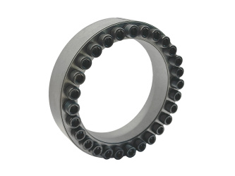
Locking assemblies are available in a wide variety of designs and types. In addition to the torsional or bending moments to be transmitted, the available installation spaces as well as loads also play an essential role for the right product selection. No matter whether self-centering, low surface pressure, high speeds or stainless steel versions for the food- and chemical-industry.
Compliant cone locking assemblies
The more compliant locking assemblies have a total of four conical functional surfaces and several individual components. Due to the design and the resulting larger cone angle, the compliant cone locking assemblies are not self-locking. This means that it is not necessary to press off the thrust rings during disassembly. Since the pressure rings are not moved axially on the shaft during assembly, there is no axial displacement between the shaft and hub.
Rigid cone locking assemblies
Rigid cone clamping elements have only one or two conical functional
surfaces. This results in different technical properties than the more
compliant cone locking assemblies. Due to their design, rigid cone
clamping elements can transmit higher bending moments. In addition, this
design has the property of better self-centering and self-locking.
Another property is that the clamping screws are not subjected to any
further loads by incoming forces during operation after assembly. This
increases the safety and service life of the rigid cone clamping
elements.
Internal clamping sets
With the internal clamping sets, hubs of all types can be fastened to commercially available shafts. The clamping sets offer the following advantages: self-centring, self-locking taper angles, increase in concentricity through pre-centring.
In general, the various locking assemblies can be subdivided according
to the type of application and the available installation space:
Short locking assemblies are usually able to absorb low to medium torsion and bending moments.
Wide locking assemblies are used for high to very high torsion and bending moments.
Product overview

___________________
Low torque transmission
Medium bending moments
Short installation lenght

___________________
Low torque transmission
Medium bending moments
Short installation lenght

___________________
Medium torque transmission
Medium bending mom.
Short installation lenght

___________________
Medium torque transmission
Medium bending mom.
Short installation lenght

___________________
Very high torque transmission
High bending moments
Wide installation lenght

___________________
High torque transmission
Medium bending moments
Wide installation lenght

___________________
Medium torque transmission
Medium bending mom.
Average installation lenght

___________________
Average torques
Average bending moments
Average installation length

___________________
Medium torque transmission
Medium bending mom.
Average installation lenght

___________________
High torque transmission
Medium bending moments
Average installation lenght

___________________
High torque transmission
Low bending moment takes place via the hub
Short installation lenght

___________________
Medium torque transmission
Medium bending moments
Small hub diameter

___________________
Medium torque transmission
Medium bending moment
Average installation lenght

___________________
Medium torque transmission
Medium bending moments
Average installation lenght

___________________
Low torque transmission
Small installation space

___________________
Very high torque transmission
Very high bending moments
Wide installation lenght
Especially for pulleys
The benefits
For industry, the performance capabilities of individual components, cost advantages, reduction of assembly times or increased lifetime play an important role in the fastening of components on rotating shafts.
A conventional method in the past was the connection via a keyway. With this type of connection, a keyway/groove is milled into the shaft. This is also done in the hub. However, milling these keyways is costly and time-consuming. Another disadvantage is also the reduction of the transmittable torque due to the weakening of the shaft. Often, a splined connection also creates movement and eventual backlash, which can affect the accuracy of a machine system and create the risk of failure.
With a friction-locked shaft-hub connection by using a locking assembly, this risk can be avoided because there is no play. The use of a locking assembly therefore ensures precision and safety. In addition, costly manufacturing processes, such as milling or grooving, can be saved.
Another advantage of using a locking assembly is the
positioning on the shaft. Unlike a groove, the locking assembly can be
moved freely on the shaft. Another advantage of using a locking assembly is the
positioning on the shaft. Unlike a groove, the locking assembly can be
moved freely on the shaft. Series such as the TAS 3015 DK locking element prevent direct movements
on the shaft during assembly. This avoids costly damage to the shaft
during assembly.
Assembly
It is installed by inserting the locking assembly between the components and the subsequent tightening of the screws. By using conical surfaces, the outer diameter increases and the inner diameter reduces. Radial pressure is built up.
The clamping forces are provided and
controlled by the screws (force-controlled). This allows the direct
compensation of the clearance between shaft and hub. The supplied
locking devices are ready for installation. To achieve proper operation
with a sufficiently high coefficient of friction, the contact surfaces
between shaft and hub must be clean and slightly oiled. Machine oil must
be used as a lubricant. The functional surfaces of the locking
assembly, threads and screw heads are prepared at the factory with oil
film.
Application examples
The use of locking assemblies is diverse and covers many different industrial sectors. From classic mechanical engineering, as well as conveyor and drive technology, to the packaging and food industries, to name just a few examples.
Finally, the locking assemblies enables precise fastening of hubs on shafts or axles, as for example in the fixation of gears and sprockets. In addition, our clamping elements/locking assemblies find applications in conveyor belt drums or crushers. In the food and also petrochemical industry, stainless versions of the locking assemblies are often used in filling or agitating equipment.
Locking assemblies are used in the packaging
industry for fastening pulleys and for transporting objects within the
machine.
Flohr Industrietechnik GmbH - Im Unteren Tal 1 - D-79761 Waldshut-Tiengen - Phone: +49 (0)7751 / 8731-0 - info@flohr-industrietechnik.de


