


Incremental encoders FGH 14

 1
1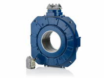 2
2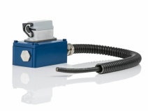 3
3Short info: Incremental encoders
- Hollow shafts up to Ø 150 mm
- B14 flange as basis to attach 4 more devices
- Up to 3600 pulses HTL / TTL
- Options: Second signal output, FOC transmitter, overspeed switch, further signal options, maintenance-friendly replacement scanning head
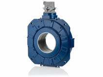
Optical rotary encoders for main drives
The incremental optical rotary encoders FGH 14 for continuous hollow shafts up to Ø 150 mm are mostly mounted directly onto the shaft. Thanks to the flat design the optical rotary encoders are ideally suitable for attaching further sensors such as speed switches, absolute encoders or combinations of these. Furthermore, there is also the option of a redundant configuration with two equal scanning systems and evaluation electronics. That increases safety or facilitates the provision of separate signals to the motor controls and a higher-level controller. The maintenance-friendly replacement of the optical rotary encoder's scanning head facilitates simple changeover without separating the motor and gearing.

| Attribute | Value |
|---|---|
| Supply voltage | 12-30 VDC |
| Signal amplitude | HTL or TTL |
| Pulse rate | 720, 1000, 1024, 1800, 3000, 3600 |
| Output signals | 0° track |
| Maximum frequency | Hollow shaft: up to 2500 rpm (up to 800 rpm with IP66) / max. 100 kHz |
| Electrical connection | Terminal box (copper cable or FOC connection), Plug-in connector (circular connector / industry quality connector), Preinstalled connection cable |
| Construction type / Ø shafts | Hollow shaft / up to Ø 150 mm |
| Device temperature range | -25 °C to +85 °C |
| Degree of protection | Up to IP66 |
| Weight | Approx. 32 kg |
| Device options | Redundant version (KK) with second terminal box |
| S: Electronic overspeed switch with two mutually independent, programmable switching points | |
| FOC: Encoder signals transmitted via a fiber optic cable | |
| 90: Second pulse track as basic track, however, electrically phase shifted by 90° | |
| N/N2: Mechanically fixed reference pulse (N), one square-wave pulse per revolution, with inverted signal | |
| G: Additional inverted output signals for basic track, 90° track, reference pulse including LED indication | |
| 2F: Twice as many basic track pulses by combining the 0° and 90° tracks | |
| B: Rapid direction of rotation sensing at each edge of 0° and 90° tracks | |
| B2: Rapid direction of rotation sensing at each edge of 0° and 90° tracks; additional standstill detection | |
| V: Electronic doubling of the basic track and 90° track pulses through multiple evaluation | |
| L2: 150 mA power output for basic track, 90° track and their associated inverted signals | |
| J: Optically adjusted pulse disk for reduced rotational frequency modulation | |
| Mechanical options | B14 flange for attachments, Maintenance-friendly replaceable scanning head, Torque bracket (on request) |
Flohr Industrietechnik GmbH - Im Unteren Tal 1 - D-79761 Waldshut-Tiengen - Phone: +49 (0)7751 / 8731-0 - info@flohr-industrietechnik.de